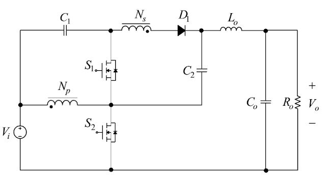

- POWER =60W
- VIN=12V
- VOUT=72V
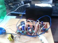
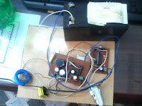
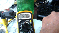
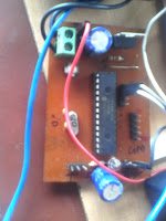
 WAVE FORMS
 s2-s1 gate signals
 output (attenuation of 10 used)
 Vds2
PROGRAM (OPEN LOOP)
//Micro controller -dspic30f2010
//compiler -mikroc
//i have used crystal of 20 MHz
//output at 50KHz
// //duty_50% = (clock_frequency/ (output_frequency*4 *1)) -1 =99
//DEAD TIME = duty_50%/2 =45
void main()
{
unsigned int pwm_period, current_duty ;
current_duty=99; //duty ratio 50% =99
pwm_period = PWM1_MC_Init(50000, 0, 0x11, 0); //enable 1L AND 1H pwm pins
PWM1_MC_Set_Duty (current_duty, 1) ;
PWM1_MC_Start();
DTCON1=10; //DEAD TIME CONTROL maximum 79
while (1);
}
PROGRAM (CLOSED LOOP)
//used crystal of 20 MHz
//output at 50KHz
// //duty_50% = (clock_frequency/ (output_frequency*4 *1)) -1 =99
//DEAD TIME = duty_50%/2 =45
//feed back by 100k and 2.2k
//adc value —295 for 67V
//char g[5];
//void adctoascii (void); //declare globally
int feedbackvoltage;
void main()
{
unsigned int pwm_period, current_duty ;
current_duty=99; //duty ratio 50% =99
pwm_period = PWM1_MC_Init(50000, 0, 0x11, 0); //enable 1L AND 1H pwm pins
PWM1_MC_Set_Duty (current_duty, 1) ;
PWM1_MC_Start();
DTCON1=10; //DEAD TIME CONTROL maximum 79
//UART1_Init(9600); // Initialize UART module at 9600 bps
//Delay_ms(100); // Wait for UART module to stabilize
//UART_Write_Text(“Start”);
//UART_Write(0xd);
TRISB.F0 = 1;
while (1)
{
feedbackvoltage = ADC1_Read(0)*67/295; Delay_ms(10);
//adctoascii ();UART_Write_Text(g);UART_Write(0xd);
//Delay_ms(100);
if(feedbackvoltage>70)
{
current_duty=current_duty-1;
if(current_duty<1)current_duty=0;
PWM1_MC_Set_Duty (current_duty, 1) ;
}
else if (feedbackvoltage<69 )
{
current_duty=current_duty+1;
if(current_duty>160)current_duty=160;
PWM1_MC_Set_Duty (current_duty, 1) ;
}
}
}